DEM simulation of granular flow in a screw feeder and a vibratory tubular feeder: A comparison study
Foad Farivar1, Danny Herrera1
- Sentinam Pty Ltd, Bassendean, WA 6054, Australia
Abstract
A DEM model is used to simulate the feeding process of a vibratory and a screw feeder. Two particle size distributions (PSD1 and PSD2) are used for each feeder to study the effect of the material size on the feeding process. The material drawdown flow patterns form the hopper are compared between the feeders by measuring the amount of material drawn from different sections of the hopper. Finally, an approximate wear profile of the feeders is presented for the comparison. The simulation results show that the vibratory feeder has more consistent feeding rate and less prone to wear.
- Introduction
Feeders are of paramount importance in a bulk material handling system to regulate and meter the flow of materials. The main objective of a feeding system is achieving a uniform and controlled flow of material without segregation and spillage [1, 2]. Uniform deposition of material on the conveyor, safety, minimising dust, and wear are other factors that should be considered in designing a feeding system [2].
Feeders are categorised into two general types of volumetric and gravimetric. Volumetric feeders such as screw, belt and vibrating feeders, are for controlling the volumetric flow rate of material from a storage bin, and gravimetric feeders such as weigh belt, are for close control of the mass flow rate of material discharge [3, 4].
The bulk material properties and application are the main factors to be considered in deciding which feeder to use [4]. For example, rotary valves are preferred over vibratory feeders for dry powders, and if materials are sensitive to pressure, belt feeders are the primary choice [5]. However, deciding which feeder to use can be challenging when there is no clear advantage of using one type over another one. For instance, vibratory feeders and screw feeders can be used interchangeably for feeding most of the non-cohesive materials in the mining industry. Therefore, other factors such as price, maintenance and flexibility need to be considered.
In this study, the Discrete Element Method (DEM) is used to simulate and compare a screw feeder to a vibratory tubular feeder for feeding revert (from Nickle smelting process) particles. DEM has been extensively used to simulate and study the flow of bulk material in various applications [6-9]. Cleary [10] employed DEM to study the drawdown of spherical and non-spherical particles from a hopper in an inclined screw feeder. The effect of rotational speed and insertion rate in a screw conveyor is investigated by Hu et al. [11]. Li et al. [12] studied the feeding ability of vibration feeder in different vibrating frequencies and input quantities. They concluded that by decreasing the vibration frequency and increasing the input, the accumulation of material increases in the system. Although there are many experimental and numerical studies on various types of feeders, comparing different types of feeder for the same application has not received much attention.
In this paper, we used Rocky 4.3 DEM software to analyse the feeding of spherical particles using a screw feeder and a vibratory feeder. Four simulations are performed for different size distribution, and the wear profile and throughput consistency of the feeders are compared.
- Simulation setup
A 3-dimensional soft-sphere DEM model [13] is used to simulate the material flow in the screw and vibratory feeders. Fig. 1 shows the general geometry of the feeding system.

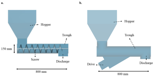

Fig. 1. The geometry of (a) screw feeder and (b) vibratory feeder.
Two simulations for each feeder is performed using two different particle size distributions (PSD). The DEM parameters are calibrated based on experimental Angle of Repose (AoF) and Drawdown Angle (DDA) of the revert particles. The simulation parameters are given in table1.
Table 1. Simulation parameters
| Parameter | Unit | Value |
| PSD 1 | Min:1, max:2 | |
| PSD 2 | Min: 2, max: 4 | |
| Particle density | 2500 | |
| Poisson’s ratio | – | 0.3 |
| Young’s module | 1.0 e+8 | |
| Statice Friction | – | 0.5 |
| Restitution coefficient | 0.5 | |
| AoR | ᵒ | 36 |
A coarse grain model (CGM) [14] for the DEM particles is used to increase the computational speed of the simulations.
- Results and Discussion
- Discharge mass
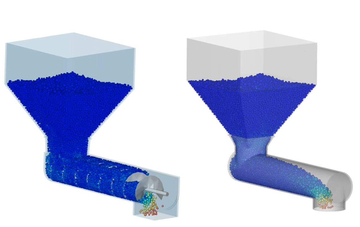
Fig. 2 shows the total discharge mass of materials from the screw and vibratory feeders for both PSDs. The initial feeding delay in the screw feeder is the time required for the materials to reach the discharge point from the hopper. For the vibratory feeder, this delay is much shorter because materials initial rest position in this feeder is close to the discharge point, as shown in Fig.3.
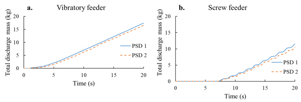
Fig. 2. Total discharge mass of (a) the vibratory feeder and (b) the screw feeder.
The slope of the discharge mass in Fig. 2 represent the feeding rate of materials. The vibratory feeder has more consistent feeding rate whereas in the screw feeder there are small changes in the feeding rate.
Both feeders’ discharge rate and total discharge mass are almost the same for PSD1 and PSD2, which shows that feeding rate in the feeders is independent of the materials size distribution.

Fig.3 Initial state of the particles in (a) vibratory and (b) screw feeders.
- Material drawdown
Even drawdown of material from the hopper is an essential criterion in a feeding system. Uneven drawdown can lead to a varying residence time of material within the hopper or storage bin and cause quality issues [15].
In order to compare the drawdown flow patterns of vibratory and screw feeders, the hopper outlet is divided into four sections of S1 to S4 (see Fig. 4). The total mass of material entering each section is measured for the feeders. Fig. 5 shows the percentage of the total material flowing out of the hopper for each section.

Fig. 4 Sections S1 to S4 at the outlet of the hopper.

Fig. 5 Material drawdown flow through sections S1 to S4 for (a) vibratory and (b) screw feeders.
The vibratory feeder draws more material from the front of the hopper whereas the screw feeder draws more material from the back end of the hopper. In both hoppers, more materials leave S3 and S4 due to the friction force between the boundaries and the particles. The results show that the PSD has no effect on drawdown flow patterns in both feeders. Special design optimisations are required for both feeders (especially the screw feeder) to achieve more even material drawdown flow patterns.
- Wear
Wear is a significant issue in any bulk material handling processes, especially when dealing with abrasive materials. Fig. 6 shows the wear profile of both feeders at the end of the feeding process. The wear is assumed to be proportional to the shear force acting at the surface of the boundaries. The ratio of volume to shear work is assumed to be for both feeders. The screw feeder’s wear rate is much higher than the vibratory feeder because materials in the screw feeder are pushed along the trough whereas in vibratory feeder materials are moved by the vibration of the trough.

Fig. 6 Wear profile of the vibratory (left) and screw (right) feeders after 20 s of the feeding process.
- Conclusion
The feeding process for a vibratory feeder and a screw feeder was simulated using a DEM model for non-cohesive spherical particles. The results showed that the discharge flow rate of the vibratory feeder is more stable than the screw feeder. The discharge rate of both feeders remained unchanged for different material size distributions. For some applications where a constant flow rate of materials with minimum variation is required, vibratory feeders can be favourable. The drawdown flow pattern of the feeders revealed that the vibratory feeder tends to draw material from the front end of the hopper and the screw feeder from the back of the hopper. Wear analysis of the feeders showed that the screw feeder is more prone to wear as there is more shear work is applied on the boundaries by the material. Therefore special care should be taken when dealing with abrasive materials in screw feeders.
In general, for non-cohesive medium to small-sized materials, vibratory feeders can be a better option for the feeding system. However, other factors such as throughput flexibility, capacity, price and availability should be carefully considered before selecting a feeder.
- References
- Rawlings, R., The Importance of Efficient Feeder Design. Bulk, July/August, 1977.
- Roberts, A., Design and application of feeders for the controlled loading of bulk solids onto conveyor belts. University of Newcastle, NSW Australia, 2012.
- Hopkins, M., Loss in weight feeder systems. Measurement and Control, 2006. 39(8): p. 237-240.
- Wang, Y., T. Li, F.J. Muzzio, and B.J. Glasser, Predicting feeder performance based on material flow properties. Powder Technology, 2017. 308: p. 135-148.
- Carson, J.W. and G. Petro, How to design efficient and reliable feeders for bulk solids. Jenike & Johanson Inc., Flow of Solids Newsletters, 2005.
- Owen, P. and P. Cleary, Prediction of screw conveyor performance using the Discrete Element Method (DEM). Powder Technology, 2009. 193(3): p. 274-288.
- Balevičius, R., R. Kačianauskas, Z. Mroz, and I. Sielamowicz, Analysis and DEM simulation of granular material flow patterns in hopper models of different shapes. Advanced Powder Technology, 2011. 22(2): p. 226-235.
- Bharadwaj, R., Using DEM to solve bulk material handling problems. Chemical Engineering Progress, 2012. 108(9): p. 54-58.
- Lommen, S., M. Mohajeri, G. Lodewijks, and D. Schott, DEM particle upscaling for large-scale bulk handling equipment and material interaction. Powder Technology, 2019. 352: p. 273-282.
- Cleary, P.W., DEM modelling of particulate flow in a screw feeder Model description. Progress in Computational Fluid Dynamics, An International Journal, 2007. 7(2-4): p. 128-138.
- Hu, G., J. Chen, B. Jian, H. Wan, and L. Liu. Modeling and simulation of transportation system of screw conveyors by the discrete element method. in 2010 International Conference on Mechanic Automation and Control Engineering. 2010. IEEE.
- Li, L., Y. Li, J. Wang, and X. Ma, SIMULATION STUDY ON THE INFLUENCE OF VARIABLE FREQUENCY AND INPUT QUANTITY ON FEEDING ABILITY OF VIBRATORY FEEDER. Academic Journal of Manufacturing Engineering, 2019. 17(3).
- Cundall, P.A. and O.D.L. Strack, A discrete numerical model for granular assemblies. Géotechnique, 1979. 29(1): p. 47-65.
- Sakai, M., M. Abe, Y. Shigeto, et al., Verification and validation of a coarse grain model of the DEM in a bubbling fluidised bed. Chemical Engineering Journal, 2014. 244: p. 33-43.
- Fernandez, J.W., P.W. Cleary, and W. McBride, Effect of screw design on hopper drawdown of spherical particles in a horizontal screw feeder. Chemical Engineering Science, 2011. 66(22): p. 5585-5601.